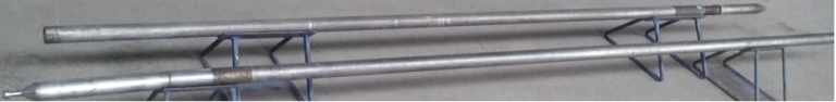
Hydraulic Expandable Stabilizer Working Principle: Real-Time Gauge Control Technology
Dual Operating Mode Mechanism
- Expansion Phase – Pumps Operating
Component Action Result
Hydraulic Piston Moves upward under pressure Activates push rods
Expandable Blades Extend radially Increase outer diameter
Locking Mechanism Engages at maximum extension Maintains position
Flow Control Valve Regulates pressure ramp rate Prevents shock loading
Expansion Sequence:
-Pump startup creates pressure increase in flow line
-Hydraulic fluid transfers pressure to piston chamber
-Mechanical linkage converts linear motion to radial blade movement
-Maximum extension achieved within 15-30 seconds of pumping
- Retraction Phase – Pumps Off
Trigger Mechanism Outcome
Pump stoppage Pressure decay in system Spring initiation
Return Springs Provide retraction force Blades pull inward
Pressure Relief Controlled bleed-off Smooth transition
Mechanical Stops Limit retraction travel Maintain minimum clearance
Retraction Process:
-Pressure drop below threshold level
-Spring force overcomes hydraulic pressure
-Blades retract to minimum diameter
-Tool ready for tripping or further adjustments
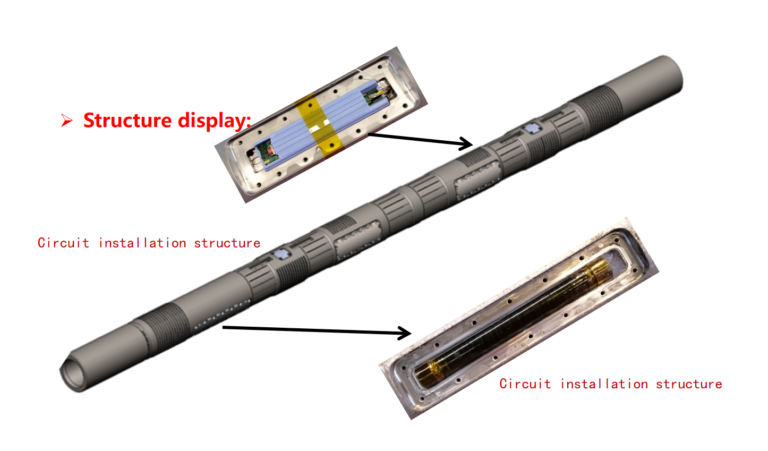
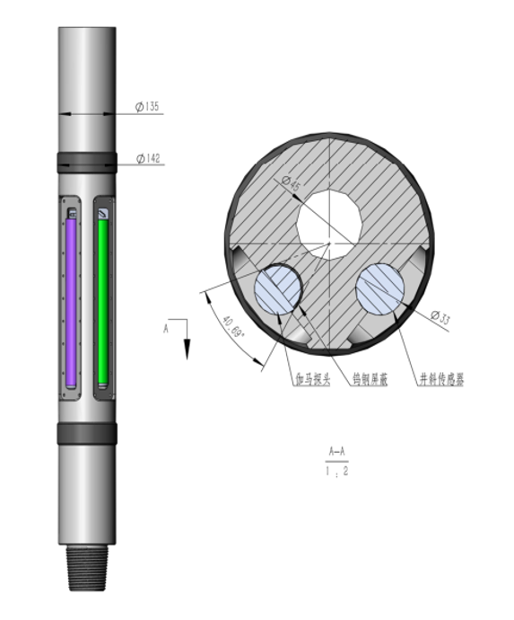
Key Components & Functions
Hydraulic Power System
Pressure Chamber: Contains hydraulic fluid, responds to mud pressure changes
Control Valve: Manages pressure application rate (300-500 psi operating range)
Piston Assembly: Converts hydraulic pressure to mechanical force
Blade Activation Mechanism
Push Rods: Transfer motion from piston to blades
Sliding Guides: Ensure parallel blade movement
Tungsten Carbide Inserts: Provide wear resistance in extended position
Safety & Control Features
Pressure Relief Valve: Prevents over-pressurization
Mechanical Stops: Limit maximum blade extension
Spring Backup: Ensures positive retraction
FDF Bypass Valve Working Principle: Emergency Circulation Mechanism
Fundamental Operating Concept
The FDF bypass valve operates on a pressure-differential activation principle, providing an alternative flow path when normal circulation through the bit becomes blocked.
Dual Operating Mode Mechanism
1. Normal Drilling Mode – Valve Closed
| Component | Status | Function |
| Main Flow Path | Open | 100% flow through bit nozzles |
| Bypass Ports | Sealed closed | Metal-to-metal seal maintained |
| Activation Piston | Hydraulically balanced | Held in upper position by spring force |
| Pressure Differential | Below threshold (500-800psi) | Valve remains in default position |
Working Process:
Drilling fluid flows freely through the tool body
Minimal pressure loss (typically 50-100psi)
Spring mechanism maintains upward force on piston
All fluid exits through bit nozzles
2. Emergency Bypass Mode – Valve Open
| Trigger Condition | Activation Mechanism | Resulting Action |
| Bit nozzle plugging | Pressure differential increases | Piston moves downward |
| 800+ psi differential | Spring compression | Ports uncovered |
| Flow obstruction | Hydraulic force overcomes spring | Alternative path established |
Activation Sequence:
Pressure Buildup: Bit nozzles plug, pressure increases upstream
Piston Movement: Differential pressure moves piston downward
Port Exposure: Bypass ports uncovered at specific stroke length
Flow Diversion: Fluid redirects through side ports
Circulation Resumed: Continuous flow maintained despite bit plugging
Key Components & Their Functions
-Differential Piston Assembly
Spring-Loaded Design: Pre-calibrated spring determines activation pressure
Balanced Seals: Dual seals prevent premature activation
Stroking Mechanism: Controlled movement ensures positive port opening
-Flow Diversion System
Side Ports: Strategically sized for adequate flow area (150-300% pipe ID)
Flow Channels: Optimized geometry for minimal turbulence
Hydraulic Expandable Stabilizer Working Principle: Real-Time Gauge Control Technology
Dual Operating Mode Mechanism
1. Expansion Phase – Pumps Operating
| Component | Action | Result |
| Hydraulic Piston | Moves upward under pressure | Activates push rods |
| Expandable Blades | Extend radially | Increase outer diameter |
| Locking Mechanism | Engages at maximum extension | Maintains position |
| Flow Control Valve | Regulates pressure ramp rate | Prevents shock loading |
Expansion Sequence:
-Pump startup creates pressure increase in flow line
-Hydraulic fluid transfers pressure to piston chamber
-Mechanical linkage converts linear motion to radial blade movement
-Maximum extension achieved within 15-30 seconds of pumping
2. Retraction Phase – Pumps Off
| Trigger | Mechanism | Outcome |
| Pump stoppage | Pressure decay in system | Spring initiation |
| Return Springs | Provide retraction force | Blades pull inward |
| Pressure Relief | Controlled bleed-off | Smooth transition |
| Mechanical Stops | Limit retraction travel | Maintain minimum clearance |
Retraction Process:
-Pressure drop below threshold level
-Spring force overcomes hydraulic pressure
-Blades retract to minimum diameter
-Tool ready for tripping or further adjustments
Key Components & Functions
Hydraulic Power System
Pressure Chamber: Contains hydraulic fluid, responds to mud pressure changes
Control Valve: Manages pressure application rate (300-500 psi operating range)
Piston Assembly: Converts hydraulic pressure to mechanical force
Blade Activation Mechanism
Push Rods: Transfer motion from piston to blades
Sliding Guides: Ensure parallel blade movement
Tungsten Carbide Inserts: Provide wear resistance in extended position
Safety & Control Features
Pressure Relief Valve: Prevents over-pressurization
Mechanical Stops: Limit maximum blade extension
Spring Backup: Ensures positive retraction